当前位置:网站首页>Data communication foundation STP principle
Data communication foundation STP principle
2022-07-26 10:10:00 【GALi_ two hundred and thirty-three】
Spanning tree protocol
Spanning tree protocol ( English :Spanning Tree Protocol,STP), It's a kind of work OSI The second layer in the network model ( Data link layer ) Communication protocol of , The basic application is to prevent loops caused by redundant links of switches . Logical topology used to ensure no loop in Ethernet . Thus avoiding the broadcast storm , Take up a lot of switch resources .
As with the development of many agreements , Spanning tree protocol is also updated with the development of network , From the initial IEEE 802.1D As defined in STP To IEEE 802.1W Fast spanning tree protocol defined in RSTP(Rapid Spanning Tree Protocol), To the latest IEEE 802.1S Multi spanning tree protocol defined in MSTP(Multiple Spanning Tree Protocol).
After deploying spanning tree protocol in Ethernet switching network , If a loop appears in the network , Spanning tree protocol through topology calculation , Can be realized :
- Eliminate the loop : By blocking redundant links, the possible network communication loops in the network are eliminated .
- Link backup : When the currently active path fails , Activate the redundant backup link , Restore network connectivity .
Spanning tree technology background
- Switch single line uplink , There is a single point of failure , Neither uplink nor equipment has redundancy , Once the link or uplink equipment fails , Business will be interrupted .

Redundant topology can solve the problem of single point of failure , But it also brings the second floor loop ;
In the actual network environment , Due to human negligence, it may also cause the second floor loop .
The second layer loop is very harmful to the network . If there is a second layer loop , Once the broadcast data frame appears , These data frames will be continuously flooded by the switch , So as to cause broadcast storm in the network , Serious consumption of equipment resources and network bandwidth , Eventually, the network will be paralyzed .

- By deploying the spanning tree in the switched network (Spanning-tree) technology , It can prevent layer 2 loops in the network .STP After operation , If there is a loop in the network , that STP Through blocking (Block) Specific interfaces to break the loop , And when the network topology changes, it converges in time , To ensure the redundancy of the network .

- When the network topology changes ,STP Can automatically converge , And adjust the interface state , So as to ensure the redundancy of the network .

STP The election process of
- Each switching network elects a root bridge (Root Bridge);
- Select a root port on each non root bridge (Root Port);
- Each segment elects a specified port (Designated Port);
- Blocking non specified ports (NonDesignated Port).
Message fields
| byte | Field | describe |
|---|---|---|
| 2 | agreement | Represents the upper layer agreement (BPDU), The value is always 0 |
| 1 | edition | (802.1D Total of 0) |
| 1 | TYPE | “ To configure BPDU” by 0、“TCN BPDU” by 80 |
| 1 | sign | LSB The least significant bit indicates TC sign ;MSB The most significant bit indicates TCA sign |
| 8 | root ID | The bridge of the root bridge ID |
| 4 | Path overhead | To the root bridge STP cost |
| 8 | Bridge ID | BPDU Sending bridge ID |
| 2 | port ID | BPDU Send the port of the bridge ID( priority + Port number ) |
| 2 | Message lifetime Message age | From the root bridge BPDU Seconds after that , Every time you pass a bridge, you will lose 1, So it is essentially the number of hops to reach the root bridge . |
| 2 | Maximum life Max age | When you haven't received any BPDU, The survival period has reached MAX age when , The bridge thinks that the link connected to this port has failed . Default 20S |
| 2 | HELLO Time | Sent continuously by the root bridge BPDU Time interval between . Default 2S |
| 2 | Forwarding delay | The time interval between monitoring and learning . Default 15S |
To configure BPDU Important parameters in
| Field | describe |
|---|---|
| Root Identifier root ID | Send this configuration BPDU The switch ID of the root switch considered by the switch |
| Root Path Cost Path cost to root | Send this configuration from BPDU The switch of arrives Root switch The total cost of the shortest path , Including the cost of switch root port , It does not include sending this configuration BPDU Port overhead |
| Bridge Identifier Bridge ID | Send this configuration BPDU Of the switch of STP Switch identification |
| Port Identifier port ID | Send this configuration BPDU Of the switch port STP Port identification |
** Comparison order :**Root Identifier > Root Path Cost> Bridge Identifier>Port Identifier
The smaller the value, the higher the priority
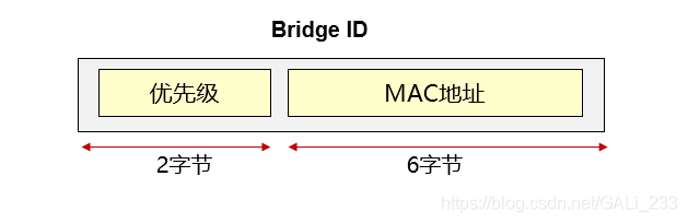
Bridge ID
Bridge ID(Bridge ID) It's a switch STP Identifier , altogether 8 Bytes , from 2 Priority of bytes and 6 Bytes of MAC Address structure :
- The bridge priority defaults to 32768, It can be modified by hand .
- MAC The address is the backplane of the switch MAC.
- In the network Bridge ID The smallest switch will be the root bridge .
Path Cost
The path cost is a port quantity , yes STP/RSTP The protocol is used to select the reference value of the link .
The default value and value range of port path cost are determined by the selected path cost algorithm , The path overhead is inversely proportional to the bandwidth of the port . namely , More bandwidth , The less it costs .
The path cost calculation standard supported by Huawei network devices :802.1d-1998、802.1t、legacy, among legacy It is Huawei's private standard . Huawei switches are selected by default 802.1t Standards for .
| bandwidth | 802.1t | 802.1d |
|---|---|---|
| 10Mbps | 2,000,000 | 100 |
| 100Mbps | 200,000 | 19 |
| 1000Mbps | 20,000 | 4 |
| 10,000Mbps | 2,000 | 2 |
It can also be seen from the above table that the larger the bandwidth , The less it costs . Overhead can be understood as “ The proportion ”.
IEEE802.1D The standard initially defined overhead as 1000Mbit/s Divide by the bandwidth of the link ( Unit is Mbit/s). for example ,10BaseT The overhead of the link is 100(1000/10), Fast Ethernet and FDDI The expenses are 10.

Port ID
port ID (2 byte )= Port priority (1 byte )+ Port number (1 byte )
Default priority 128, Range 0-255, The smaller the better .

Specific election process
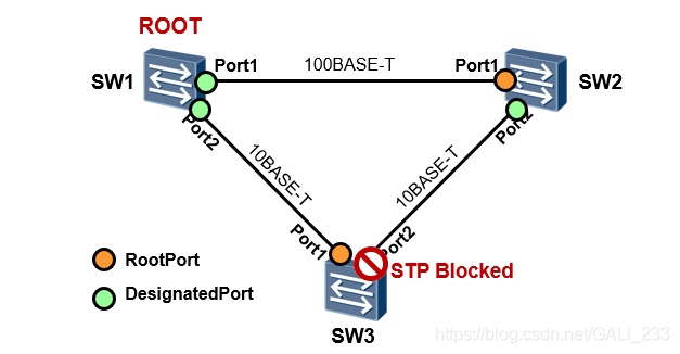
1. Each switching network elects a root bridge (Root Bridge);
In the network Bridge ID The smallest switch is elected as the root bridge .
Equal priority , Compare mac The address is small , therefore SW1 by Root Bridge.

2. Select a root port on each non root bridge (Root Port);
Except for the root switch (SW1), Other switches choose the root port , Compare Path cost( Port overhead from root switch to non root switch ).
With SW3 For example ,
Port1 The cost of = SW1 To SW3 Of Port1 Port overhead (10BASE-T)
Port2 The cost of = SW1 To SW2 Of Port1 Port overhead + SW2 To SW3 Of Port2 Port overhead (100BASE-T + 10BASE-T)
Here, the superposition of the cost value refers to the superposition of the cost of the input port .
Obviously Port1 The cost is small , So the priority is high ,Port1 For the root port .
Again ,SW2 Of port1 expenses = (100BASE-T),port2 expenses = (10BASE-T + 10BASE-T), Because the larger the bandwidth , The less it costs , therefore port1 For the root port .
3. Each segment elects a specified port (Designated Port);
All ports on the root bridge are designated ports , So just in SW2 And SW3 Between elections
Router ID identical , Compare Path cost,
SW3port2 The cost of = (10BASE-T +10BASE-T)
SW2port2 The cost of = (100BASE-T +10BASE-T) , Low overhead , Select as the specified port 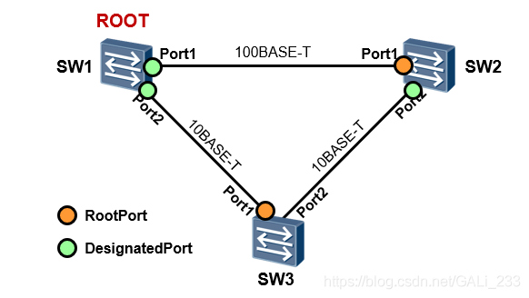
4.1. Select an unspecified port (NonDesignated Port), Non specified ports will be blocked .
The unselected port will become a blocked port

STP Port status of
| Disable | Ports not only do not forward BPDU message , And don't forward user traffic . Port is DOWN |
|---|---|
| Blocking | The port only receives and processes BPDU, Do not forward user traffic . Don't work MAC Address . If max age( Default 20s) When the timer expires, the interface does not receive BPDU Then switch to Listening state . |
| Listening | Do not receive or forward user traffic , Receive and send BPDU, Don't work MAC Address Determine the port role , There will be an election . |
| Learning | Do not receive or forward user traffic , Receive and send BPDU, Study MAC Address |
| Forwarding | Receive and forward frames , Receive and send BPDU, Study MAC Address |

STP Topology change mechanism
When topology changes in the network , For example, the link is interrupted or the interface is abnormal Down , etc. , because MAC The existence of address aging time ( Default is 5 minute ), If the upstream equipment is not notified in time , It may cause the message of the upstream device to be sent to an unreachable link all the time during this period .
Reference resources :STP Topology change mechanism


Link failure is sensed , The downstream equipment will continuously send TCN BPDU message ,
Upstream equipment will configure BPDU In the message Flags Of TC Bit and TCA Bits are set at the same time 1, Then send it to the downstream equipment , Inform downstream equipment to stop sending TCN BPDU message
Upstream equipment , take TCN BPDU Make a copy and send it to genbashi , Until genqiao receives TCN BPDU message .
Root bridge handle configuration BPDU In the message Flags Of TC Bit and TCA Bits are set at the same time 1 Post send ,TC Location 1 This is to notify the downstream equipment to delete the bridge directly MAC Address table entry ,TCA Location 1 This is to notify the downstream device to stop sending TCN BPDU message .

So-called “cam surface ” It means two bai Running on layer switch Cisco IOS A table maintained in memory ,CAM Table is the table that the switch will look up when forwarding data at layer 2 , Table has MAC Address , Corresponding port number , The port belongs to VLAN. Each layer-2 port of the switch has MAC Address automatic learning function , When the switch receives PC Sent a frame , Will view the source in the frame MAC Address , And find CAM surface , If there is, do nothing , Start forwarding data . If not, deposit it CAM surface , So that others can give this MAC When sending data on the address , You can decide which port to forward data to .
Reference resources : What is? CAM surface
STP To configure
 Specify the spanning tree protocol type (STP/RSTP/MSTP):
[SW] stp mode { stp | rstp | mstp }		 The default is MSTP
 Configure switch priority :
[SW] stp priority pri			 The default is 32768
 Specify the switch as the root bridge :
[SW] stp root primary
 Specify that the switch become a secondary root bridge :
[SW] stp root secondary
 Enable spanning tree :
[SW] stp enable
 Configure interface STP priority :
[SW] interface GigabitEthernet0/0/24
[SW-GigabitEthernet0/0/24] stp priority priority
 Configure interface path overhead :
[SW] interface GigabitEthernet0/0/24
[SW-GigabitEthernet0/0/24] stp cost cost

• Start the spanning tree on three switches , The agreement types are STP( Default on mstp);
• Make... By configuration SW1 Become the main root ,SW2 Become a secondary root ;
• Final SW3 Of GE0/0/22 The interface will be STP Blocking .
SW1 The configuration is as follows :
[SW1] stp mode stp
[SW1] stp enable
[SW1] stp root primary
SW2 The configuration is as follows :
[SW2] stp mode stp
[SW2] stp enable
[SW2] stp root secondary
SW3 The configuration is as follows :
[SW2] stp mode stp
[SW2] stp enable
use SW1 see stp The result of the election

see SW3 The port of

STP The short board

If running on a switch based on VLAN The spanning tree of can solve the above problem , Because the spanning tree is perVLAN Of , Then we can flexibly set each VLAN The interface blocked by the corresponding spanning tree , So as to realize the diversion of data .
But if the network VLAN There are more of them , For each VLAN Performing independent spanning tree calculation will consume a lot of resources of the switch .
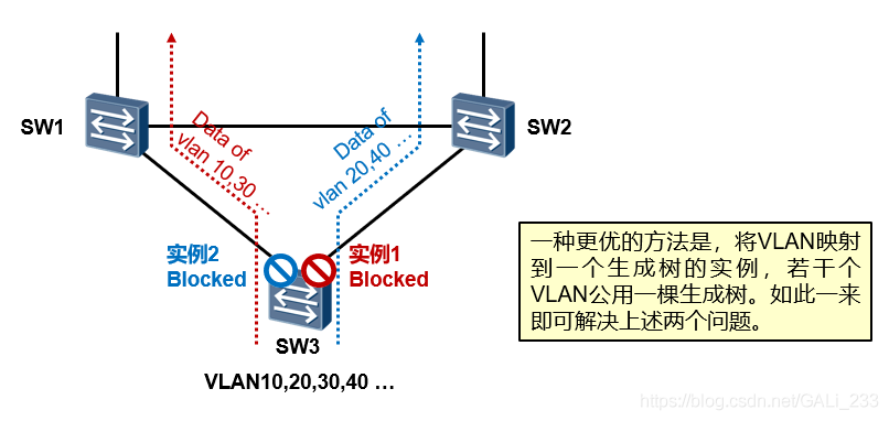
MSTP
MSTP compatible STP and RSTP, Through multiple instances, you can realize the isolation of business traffic and user traffic , It also provides multiple redundant paths for data forwarding , In the process of data forwarding VLAN Data load balancing .
stay MSTP in , You can put several VLAN Map to an instance (instance),MSTP Will be for each instance Run a spanning tree , Can be based on instance set priority 、 Port path overhead and other parameters .

about Instance1,GE0/0/22 For blocking ports ,vlan10 and vlan20 Data traffic from GE0/0/21 get out ;
about Instance2,GE0/0/21 For blocking ports ,vlan30 and vlan40 Data traffic from GE0/0/22 get out .
Configuration to realize
SW1 Configuration of
[SW1]vlan batch 10 20 30 40
[SW1]stp mode mstp                 # Set the spanning tree mode to MSTP
[SW1]stp region-configuration      # Get into MSTP The configuration view
[SW1-mst-region]region-name RG1     #MSTP The domain name is RG1
[SW1-mst-region]instance 1 vlan 10 20    # To configure VLAN Mapping to instances
[SW1-mst-region]instance 2 vlan 30 40
[SW1-mst-region]active region-configuration  # Activate MST Domain configuration
[SW1-mst-region]quit
Be careful : The domain name of the switch under the same domain name should be consistent
SW2 and SW3 The configuration is the same as above
[SW2]vlan batch 10 20 30 40
[SW2]stp mode mstp
[SW2]stp region-configuration
[SW2-mst-region] region-name RG1
[SW2-mst-region] instance 1 vlan 10 20
[SW2-mst-region] instance 2 vlan 30 40
[SW2-mst-region] active region-configuration
[SW2-mst-region]quit
[SW3]vlan batch 10 20 30 40
[SW3]stp mode mstp
[SW3]stp region-configuration
[SW3-mst-region] region-name RG1
[SW3-mst-region] instance 1 vlan 10 20
[SW3-mst-region] instance 2 vlan 30 40
[SW3-mst-region] active region-configuration
[SW3-mst-region]quit
# Configure the priority of each instance ,SW1 Configure as instance 1CIST The taproot of 、 example 2 Secondary root of :
[SW1]stp instance 1 root primary       # perhaps stp instance 1 priority 0
[SW1]stp instance 2 root secondary    # perhaps stp instance 2 priority 4096
[SW1]stp enable            # function STP
SW1 Configure as instance 2CIST The taproot of 、 example 1 Secondary root of
[SW2]stp instance 1 root secondary
[SW2]stp instance 2 root primary
[SW2]stp enable
The interface of the switch can be configured through different vlan The data of
[SW1]interface GigabitEthernet 0/0/24
[SW1-GigabitEthernet0/0/24]port link-type trunk
[SW1-GigabitEthernet0/0/24]port trunk allow-pass vlan 10 20 30 40
[SW1]interface GigabitEthernet 0/0/21
[SW1-GigabitEthernet0/0/21]port link-type trunk
[SW1-GigabitEthernet0/0/21]port trunk allow-pass vlan 10 20 30 40
[SW2]interface GigabitEthernet 0/0/24
[SW2-GigabitEthernet0/0/24]port link-type tr
[SW2-GigabitEthernet0/0/24]port link-type trunk
[SW2-GigabitEthernet0/0/24]port trunk allow-pass vlan 10 20 30 40
[SW2]interface GigabitEthernet 0/0/22
[SW2-GigabitEthernet0/0/22]port link-type trunk
[SW2-GigabitEthernet0/0/22]port trunk allow-pass vlan 10 20 30 40
[SW3]interface GigabitEthernet 0/0/21
[SW3-GigabitEthernet0/0/21]port link-type trunk
[SW3-GigabitEthernet0/0/21]port trunk allow-pass vlan 10 20 30 40
[SW3]interface GigabitEthernet 0/0/22
[SW3-GigabitEthernet0/0/22]port link-type trunk
[SW3-GigabitEthernet0/0/22]port trunk allow-pass vlan 10 20 30 40
Final effect 

You can see it here instance1 in GigabitEthernet 0/0/22 Blocking ,instance2 in GigabitEthernet 0/0/21 Blocking , So as to realize load sharing .
instance0 By default , Unmapped vlan It's all here. .
边栏推荐
- Flask framework beginner-03-template
- Replay the snake game with C language (II) end
- Interview shock 68: why does TCP need three handshakes?
- 点赞,《新程序员》电子书限时免费领啦!
- Beginner of flask framework-04-flask blueprint and code separation
- Cloud native (36) | introduction and installation of harbor in kubernetes
- The fourth week of summer vacation
- 分布式网络通信框架:本地服务怎么发布成RPC服务
- Like, "new programmer" e-book is free for a limited time!
- Study notes of the first week of sophomore year
猜你喜欢
Development to testing: a six-year road to automation starting from 0
![[MySQL database] a collection of basic MySQL operations - the basis of seeing (adding, deleting, modifying, and querying)](/img/a7/b3bb6f584dff0eb9b49e81e5b9dade.png)
[MySQL database] a collection of basic MySQL operations - the basis of seeing (adding, deleting, modifying, and querying)

AR model in MATLAB for short-term traffic flow prediction

B站这个视频我是跪着看完的

Wechat applet learning notes 1

Mysql5.7.25 master-slave replication (one-way)

R language ggplot2 visualization: align the legend title to the middle of the legend box in ggplot2 (default left alignment, align legend title to middle of legend)

Spolicy request case
![Sqoop [environment setup 01] CentOS Linux release 7.5 installation configuration sqoop-1.4.7 resolve warnings and verify (attach sqoop 1 + sqoop 2 Latest installation package +mysql driver package res](/img/8e/265af6b20f79b21c3eadcd70cfbdf7.png)
Sqoop [environment setup 01] CentOS Linux release 7.5 installation configuration sqoop-1.4.7 resolve warnings and verify (attach sqoop 1 + sqoop 2 Latest installation package +mysql driver package res
![[datawhale] [machine learning] Diabetes genetic risk detection challenge](/img/98/7981af7948feb73168e5200b3dfac9.png)
[datawhale] [machine learning] Diabetes genetic risk detection challenge
随机推荐
Force deduction DFS
SSG framework Gatsby accesses the database and displays it on the page
PMM (percona monitoring and management) installation record
Solve proxyerror: CONDA cannot proceed due to an error in your proxy configuration
Interpretation of the standard of software programming level examination for teenagers_ second level
Principle analysis and source code interpretation of service discovery
Jpg to EPS
Flask框架初学-03-模板
In Net 6.0
Transform between tree and array in JS (hide the children field if the child node of the tree is empty)
Write a script that can run in Bash / shell and PowerShell
Applet record
Opencv image processing
数通基础-网络基础知识
【Datawhale】【机器学习】糖尿病遗传风险检测挑战赛
Uniapp "no mobile phone or simulator detected, please try again later" and uniapp custom components and communication
Uni app learning summary
Distributed network communication framework: how to publish local services into RPC services
protobuf的基本用法
Uniapp error 7 < Map >: marker ID should be a number