当前位置:网站首页>05 central processing unit
05 central processing unit
2022-07-19 03:07:00 【Miss Qi】
CPU The function and structure of
![[ Failed to transfer the external chain picture , The origin station may have anti-theft chain mechanism , It is suggested to save the pictures and upload them directly (img-51zKgBS6-1657716190848)(C:\Users\DELL\AppData\Roaming\Typora\typora-user-images\image-20220710175707069.png)]](/img/14/5353014df214ed1cee0c772abcf86a.png)
![[ Failed to transfer the external chain picture , The origin station may have anti-theft chain mechanism , It is suggested to save the pictures and upload them directly (img-K3QdCWXW-1657716190849)(C:\Users\DELL\AppData\Roaming\Typora\typora-user-images\image-20220710175753750.png)]](/img/60/1f8b7d979c1a605140df4f98f591ba.png)
CPU The function of
1. Command control . Complete the command 、 Analyzing and executing instructions , The sequence control of the program .
2. Operational control . The function of an instruction is often realized by the combination of several operation signals .CPU Manage and generate the operation signal of each instruction fetched from memory , Send various operation signals to corresponding parts , In order to control these parts according to the command to carry out the action .
3. time control . Time control of various operations . Time control shall provide due control signals for each instruction in chronological order .
4. The data processing . Arithmetic and logic operations on data .
5. Interrupt handling . To deal with the abnormal situation and special request in the process of computer operation .
Functions of arithmetic unit and controller
Arithmetic unit : Process the data
controller : Coordinate and control the sequence of instructions for the execution of programs by computer components , The basic functions include taking instructions 、 Analysis instructions 、 Execution instruction
- Take command : Automatically form instruction address ; Automatically issue the command to take the instruction .
- Analysis instructions : Opcode decoding ( Analyze what this command is going to do ); The valid address of the generated operands .
- Execution instruction : According to the analysis instructions “ Operation command ” and “ Operand address ”, Form operation signal control sequence , Control arithmetic unit 、 Memory and I/O The equipment completes the corresponding operation .
- Interrupt handling : Management bus and I / O ; Handling exceptions ( Such as power failure ) And special requests ( If the printer requests to print a line of characters ).
Basic structure of arithmetic unit
![[ Failed to transfer the external chain picture , The origin station may have anti-theft chain mechanism , It is suggested to save the pictures and upload them directly (img-2z8g5eDx-1657716190850)(C:\Users\DELL\AppData\Roaming\Typora\typora-user-images\image-20220710173656843.png)]](/img/ba/bcdb4e4c2e702065b8ca852f3cf02b.png)
1. Arithmetic logic unit : The main function is to do arithmetic / Logical operations .
2. General register group : Such as AX、BX、CX、DX、SP etc. , Used to store operands ( Including source operands 、 Destination operands and intermediate results ) And all kinds of address information, etc .SP It's a stack pointer , Used to indicate the address at the top of the stack . The number of digits is equal to the machine word length , Easy to operate and control .
![[ Failed to transfer the external chain picture , The origin station may have anti-theft chain mechanism , It is suggested to save the pictures and upload them directly (img-XNRfQRNt-1657716190850)(C:\Users\DELL\AppData\Roaming\Typora\typora-user-images\image-20220710173759361.png)]](/img/f7/3c134225bf29edec9f52d9760bd116.png)
Dedicated data path side requirements : Arrange the connection line according to the flow direction of data and address in the process of instruction execution .
If connected directly with wires , It is equivalent to multiple registers simultaneously and all the way to ALU To transmit data
resolvent 1. A multiplexer is used to select one output according to the control signal
![[ Failed to transfer the external chain picture , The origin station may have anti-theft chain mechanism , It is suggested to save the pictures and upload them directly (img-ed0LkaMC-1657716190851)(C:\Users\DELL\AppData\Roaming\Typora\typora-user-images\image-20220710174104211.png)]](/img/96/454484d926eefc43a7a49d0a5c5921.png)
resolvent 2. Three state gate can be used to control whether each channel outputs
![[ Failed to transfer the external chain picture , The origin station may have anti-theft chain mechanism , It is suggested to save the pictures and upload them directly (img-hfFLKHcO-1657716190851)(C:\Users\DELL\AppData\Roaming\Typora\typora-user-images\image-20220710174207096.png)]](/img/b3/51854e96851b46e837fb7a270aeb4e.png)
Higher performance , There is basically no data conflict , But the structure is complex , Large amount of hardware , It's not easy to achieve .
CPU Internal single bus mode : Connect the input and output of all registers to a common path .
![[ Failed to transfer the external chain picture , The origin station may have anti-theft chain mechanism , It is suggested to save the pictures and upload them directly (img-BX5g19b0-1657716190852)(C:\Users\DELL\AppData\Roaming\Typora\typora-user-images\image-20220710174420437.png)]](/img/bb/386aa4e4a20a381b2317aef4627465.png)
Simple structure , Easy to implement , But there are many conflicts in data transmission , Low performance .
3. Temporary register : Used to temporarily store data read from main memory , This data cannot be stored in the general register , Otherwise, it will destroy its original content . Such as : The two operands are from main memory and R., The final result is saved back R., Then the operands obtained from main memory are directly put into the register , It will not destroy the pre operation R. The content of .
![[ Failed to transfer the external chain picture , The origin station may have anti-theft chain mechanism , It is suggested to save the pictures and upload them directly (img-6Z8PFxkI-1657716190853)(C:\Users\DELL\AppData\Roaming\Typora\typora-user-images\image-20220710174510736.png)]](/img/02/04eb69ca090bbfc0249778fef5a887.png)
![[ Failed to transfer the external chain picture , The origin station may have anti-theft chain mechanism , It is suggested to save the pictures and upload them directly (img-fc0ouGkH-1657716190853)(C:\Users\DELL\AppData\Roaming\Typora\typora-user-images\image-20220710174747211.png)]](/img/c3/2441e717a345e17057bb271ce80641.png)
4. Accumulation register : It's a general-purpose register , For temporary storage ALU The result information of the operation , It is used to implement addition operation .
5. Program status word register : All kinds of state information established by the result of arithmetic logic operation instruction or test instruction are retained , Such as overflow flag (OP)、 sign indicator (SF)、 Zero mark (ZF)、 Carry mark (CF) etc. .PSW These bits participate in and determine the formation of micro operations . It consists of two parts , First, the status flag , Twenty control signs .
6. Shifter : Shift the result .
![[ Failed to transfer the external chain picture , The origin station may have anti-theft chain mechanism , It is suggested to save the pictures and upload them directly (img-2QPXL2T6-1657716190854)(C:\Users\DELL\AppData\Roaming\Typora\typora-user-images\image-20220710174904861.png)]](/img/a9/e87ea423b4f5dfea2b09778ed0a8e3.png)
The basic structure of the controller
1. Program counter PC: Used to indicate the location of the next instruction in main memory .CPU It is based on PC To fetch instructions from main memory . Because the instructions in the program ( Usually ) It's sequential , therefore PC It has self increasing function . The number of bits of the program counter is equal to the number of bits of the memory address , And the memory address depends on the capacity of the memory .
2. Instruction register IR: It is used to save the currently executing instruction . No user intervention is required , Transparent to users . The number of bits depends on the instruction word length .
3. Instruction decoder : Only the opcode field is decoded , Provide specific operation signals to the controller .
4. Micromanipulation signal generator : according to IR The content of ( Instructions )、PSW The content of ( State information ) Just in time signals , Produce all kinds of control signals needed to control the whole computer system , Its structure has two kinds of combinational logic and storage logic .
5. Sequential systems : Used to generate all kinds of timing signals , They are all made up of a unified clock (CLOCK) Divide the frequency to get .
6. Memory address register MDR: It is used to store the address of the main memory unit to be accessed .
7. Memory data register MAR: It is used to store information written to or read from main memory .
![[ Failed to transfer the external chain picture , The origin station may have anti-theft chain mechanism , It is suggested to save the pictures and upload them directly (img-yA6YgGYN-1657716190855)(C:\Users\DELL\AppData\Roaming\Typora\typora-user-images\image-20220710175437668.png)]](/img/38/abd4f3da04665b9b73b8b7bc469ba6.png)
The controller consists of program counter PC, Instruction register IR, Memory address register MAR, Memory data register MDR, Instruction decoder , Sequential circuit and micro operation generator .
![[ Failed to transfer the external chain picture , The origin station may have anti-theft chain mechanism , It is suggested to save the pictures and upload them directly (img-96Oq3uhl-1657716190856)(C:\Users\DELL\AppData\Roaming\Typora\typora-user-images\image-20220710175520845.png)]](/img/6c/635828fa062900982ffed805412a2f.png)
Instruction execution process
![[ Failed to transfer the external chain picture , The origin station may have anti-theft chain mechanism , It is suggested to save the pictures and upload them directly (img-Ej8sSR6Y-1657716190856)(C:\Users\DELL\AppData\Roaming\Typora\typora-user-images\image-20220710183209772.png)]](/img/13/076aa18c6d4f90949c2d2da9be4ac0.png)
Instruction cycle
Instruction cycle :CPU The total time required to fetch and execute each instruction from main memory .
Instruction cycles often take several Machine cycle To express , Machine cycle is also called CPU cycle .
A machine cycle contains several clock cycles ( Also called beat 、T Cycle or CPU Clock cycle , It is CPU The most basic unit of operation ).
![[ Failed to transfer the external chain picture , The origin station may have anti-theft chain mechanism , It is suggested to save the pictures and upload them directly (img-1UOmsYlz-1657716190857)(C:\Users\DELL\AppData\Roaming\Typora\typora-user-images\image-20220710180112231.png)]](/img/23/a29c76238fa835cba6c4d9cb1fe97e.png)
![[ Failed to transfer the external chain picture , The origin station may have anti-theft chain mechanism , It is suggested to save the pictures and upload them directly (img-L5pEuf6J-1657716190858)(C:\Users\DELL\AppData\Roaming\Typora\typora-user-images\image-20220710180150544.png)]](/img/5c/ef38cd9557df66230eb017a528a254.png)
The number of machine cycles per instruction cycle can vary , The number of beats per machine cycle can also vary .
![[ Failed to transfer the external chain picture , The origin station may have anti-theft chain mechanism , It is suggested to save the pictures and upload them directly (img-iWhqgwsA-1657716190858)(C:\Users\DELL\AppData\Roaming\Typora\typora-user-images\image-20220710180935147.png)]](/img/fe/947d4bc46a0c66787222005938d58c.png)
The difference of various cycles
- The clock cycle is the smallest unit of time for computer operation , Determined by the dominant frequency of the computer , Is the reciprocal of the dominant frequency . The working pulse is the smallest time unit of the controller , rise i Timed trigger action , A clock cycle has a working pulse .
- The instruction cycle can consist of multiple CPU Cycle composition .
- CPU Cycle is machine cycle , Contains several clock cycles .
- Access cycle refers to two independent memory operations of the memory ( Two consecutive read or write operations ) Minimum interval required between .
Instruction cycle flow
![[ Failed to transfer the external chain picture , The origin station may have anti-theft chain mechanism , It is suggested to save the pictures and upload them directly (img-TQ4Ua0sZ-1657716190860)(C:\Users\DELL\AppData\Roaming\Typora\typora-user-images\image-20220710181047811.png)]](/img/f3/79b76cb0c73c957c9578463c3ef12d.png)
All four work cycles have CPU Memory access operation , It's just that the purpose of deposit access is different . The fetch cycle is to fetch instructions , The inter address period is to get a valid address , The execution cycle is for fetching operands , Interrupt cycle is to save program breakpoints .
![[ Failed to transfer the external chain picture , The origin station may have anti-theft chain mechanism , It is suggested to save the pictures and upload them directly (img-p9EYsHdj-1657716190861)(C:\Users\DELL\AppData\Roaming\Typora\typora-user-images\image-20220710181212784.png)]](/img/3f/524cf4833ade3b63bdaf6aee69f753.png)
Instruction cycle data flow - Take the period
The first machine cycle of the instruction cycle is the fetch cycle , That is, fetch the instruction word from the main memory .
1. The current instruction address is sent to the memory address register , Remember to do :(PC)→MAR
2.CU Send out control signals , Transfer to main memory via control bus , Here's the read signal , Remember to do :1→R
3. take MAR The contents of the main memory are sent to... Via the data bus MDR, Remember to do :M(MAR)→ MDR
4.CU Send out control signals , Form the next instruction address , Remember to do :(PC)+1 →PC
![[ Failed to transfer the external chain picture , The origin station may have anti-theft chain mechanism , It is suggested to save the pictures and upload them directly (img-MLszFVZk-1657716190861)(C:\Users\DELL\AppData\Roaming\Typora\typora-user-images\image-20220710181456883.png)]](/img/03/470bc17ac75141f8e1abee8664a2db.png)
After taking the finger ,PC Automatic addition 1, In the execution cycle , If PC It needs to be modified to jump to the address , You need to +1
Instruction cycle data flow - Interdigital period
1. Send the address code of the instruction to MAR, Remember to do : Ad(IR) →MAR or Ad(MDR)→MAR
2.CU Send out control signals , Start the main memory to read , Remember to do :1→R
3. take MAR The contents of the main memory are sent to... Via the data bus MDR, Remember to do :M(MAR)→MDR
4. Send the valid address to the address code field of the instruction , Remember to do :(MDR)→ Ad(IR)
![[ Failed to transfer the external chain picture , The origin station may have anti-theft chain mechanism , It is suggested to save the pictures and upload them directly (img-Ok1EcjO5-1657716190862)(C:\Users\DELL\AppData\Roaming\Typora\typora-user-images\image-20220710181730484.png)]](/img/89/d03d364c296f4dbed207dca1561bf8.png)
Memory is accessed through formal address , Register address accesses memory through register contents .
The memory itself cannot distinguish whether instructions or data are stored in the storage unit . Under the control of the controller , The computer reads the memory at different stages / When writing operations , The extracted code has different uses , The binary code read out in the fetch phase is the instruction , The code retrieved during execution may be data .
Instruction cycle data flow - Execution cycle
The task of the execution cycle is based on IR The opcodes and operands of the instruction words in the ALU Operations produce execution results . Different instructions have different execution cycles , So there is no unified data flow .
Instruction cycle data flow - Interrupt cycle
![[ Failed to transfer the external chain picture , The origin station may have anti-theft chain mechanism , It is suggested to save the pictures and upload them directly (img-uCiMb2vD-1657716190862)(C:\Users\DELL\AppData\Roaming\Typora\typora-user-images\image-20220710182353921.png)]](/img/2a/3eb2a53a619cd067bff1f2f94f248c.png)
interrupt : Pause the current task to complete other tasks . In order to be able to resume the current mission , Need to save breakpoints . The stack is usually used to hold breakpoints , Here we use SP Represents the top of the stack address , hypothesis SP Point to the top element of the stack , The stack operation is to modify the pointer first , And then store the data .
1.CU Control will SP reduce 1, The modified address is sent to MAR Remember to do :(SP)-1 →SP,(SP) → MAR
It's essentially storing a breakpoint in a storage location , Suppose its address is a, So you can remember to do : a →MAR
2.CU Send out control signals , Start the main memory to write , Remember to do :1→w
3. Break point (PC Content ) Send in MDR, Remember to do :(PC)→ MDR
4.CU Control will interrupt the entry address of the service program ( Generated by the vector address forming unit ) Send in PC, Remember to do : Vector address →PC
Instruction execution scheme
An instruction cycle usually includes several time periods ( Execution steps ), Each step completes part of the function of the instruction , Several sequential steps complete all the functions of this instruction .
![[ Failed to transfer the external chain picture , The origin station may have anti-theft chain mechanism , It is suggested to save the pictures and upload them directly (img-8cYqwGP5-1657716190862)(C:\Users\DELL\AppData\Roaming\Typora\typora-user-images\image-20220710182612181.png)]](/img/d1/4bbd546cb15c5149583b2671eda683.png)
programme 1. Single instruction cycle
Choose the same execution time for all instructions . Serial execution between instructions ; The instruction cycle depends on the execution time of the instruction with the longest execution time .
For instructions that could have been completed in a shorter time , Use this longer cycle to complete , It will reduce the running speed of the whole system .
programme 2. Multiple instruction cycles
Select different execution steps for different types of instructions . Serial execution between instructions ; Different number of clock cycles can be selected to complete the execution of different instructions .
Need more complex hardware design .
programme 3. Pipeline solution
Start an instruction at each clock cycle , Try to run multiple instructions at the same time , But they are in different steps of execution . Instructions are executed in parallel .
Data access
![[ Failed to transfer the external chain picture , The origin station may have anti-theft chain mechanism , It is suggested to save the pictures and upload them directly (img-f3MPvM1U-1657716190863)(C:\Users\DELL\AppData\Roaming\Typora\typora-user-images\image-20220711092752900.png)]](/img/c8/6a09d0f4f0feb36945932c314de2e0.png)
use CPU Characteristics of data path in internal bus mode : Simple structure , Implement easily , Low performance , There are many conflicts .
Do not use CPU The data path of internal bus mode is characterized by : Complicated structure , Large amount of hardware , It's not easy to achieve , High performance , There is basically no data conflict .
Single bus structure
![[ Failed to transfer the external chain picture , The origin station may have anti-theft chain mechanism , It is suggested to save the pictures and upload them directly (img-lmByV3Ct-1657716190863)(C:\Users\DELL\AppData\Roaming\Typora\typora-user-images\image-20220711083929064.png)]](/img/65/e80181e34c45f2dd2f77d61d5e20c9.png)
An internal bus is the same component , Such as CPU Internal connection between the registers and the bus between the computing units ;
System bus refers to the components of the same computer system , Such as CPU、 Memory 、 Access and all kinds of l/O A bus that connects interfaces .
because ALU It's a combinational logic circuit , Therefore, the contents of the two inputs must be kept unchanged during the operation , And because of CPU The internal adopts single bus structure , So in order to get two different operands ,ALU One input of the is connected to the bus , The other input needs to be connected to the bus through a register . Besides ,ALU The output of can not be directly connected to the internal bus , Otherwise, its output is fed back to the input through the bus , Affect the operation result , Therefore, the output end needs to pass through a register ( A register used to temporarily store results ) Connected to the bus .
1. Data transfer between registers
For example PC Content sent to MAR, The process and control signal to realize the transmission operation are :
(PC)→Bus PCout It works ,PC Content delivery bus
Bus→MAR MARin It works , The bus content is sent to MAR
It's important to describe the flow of data
2. Main memory and CPU Data transfer between
![[ Failed to transfer the external chain picture , The origin station may have anti-theft chain mechanism , It is suggested to save the pictures and upload them directly (img-iR4OR10t-1657716190863)(file://C:\Users\DELL\AppData\Roaming\Typora\typora-user-images\image-20220711084258429.png?lastModify=1657500494)]](/img/8b/e3c0b1f3b6c27d6c2444bb240dc22e.png)
such as CPU Read instructions from main memory , The process and control signal to realize the transmission operation are :
(PC)→Bus→MAR PCout and MARin It works , Current instruction address →MAR
1→R CU Issue a read command ( Through the control bus , There is no picture of )
MEM(MAR)→MDR MDRin It works
MDR→Bus→IR MDRout and IRin It works , Current directive →IR
![[ Failed to transfer the external chain picture , The origin station may have anti-theft chain mechanism , It is suggested to save the pictures and upload them directly (img-x7YdMh9h-1657716190864)(C:\Users\DELL\AppData\Roaming\Typora\typora-user-images\image-20220711084816063.png)]](/img/ed/593960e9850e7de6b30f0d9968e32d.png)
3. To perform arithmetic or logical operations
Like an addition instruction , The micro operation sequence and control signal are :
Ad(IR)→Bus→MAR MDRout and MARin Effective or AdlRout and MARin It works
1→R CU Issue a read command
MEM(MAR)→ cable →MDR MDRin It works
MDR→Bus→Y MDRout and Yin It works , Operands →Y
(ACC)+(Y)→z ACCout and ALUin It works ,CU towards ALU Send plus command
Z→ACC Zout and ACCin It works , result →ACC
![[ Failed to transfer the external chain picture , The origin station may have anti-theft chain mechanism , It is suggested to save the pictures and upload them directly (img-UrKge5N8-1657716190864)(C:\Users\DELL\AppData\Roaming\Typora\typora-user-images\image-20220711085255261.png)]](/img/b7/cb2325f807069c78a8e3917a05e9ef.png)
Example
![[ Failed to transfer the external chain picture , The origin station may have anti-theft chain mechanism , It is suggested to save the pictures and upload them directly (img-p3GAtEbF-1657716190864)(C:\Users\DELL\AppData\Roaming\Typora\typora-user-images\image-20220711085519354.png)]](/img/9b/bffdc5aefb4d9ea7adef4609353809.png)
There is a single bus structure as shown in the figure , Analysis instructions ADD (RO),R1 The instruction flow and control signal of the system .
1. Analyze instruction function and instruction cycle
function :((R0))+(R1)→(R0)
Take the period 、 Interval period 、 Execution cycle
2. Write the instruction flow of each stage
Take the period : Public operation
![[ Failed to transfer the external chain picture , The origin station may have anti-theft chain mechanism , It is suggested to save the pictures and upload them directly (img-JQwOIqLK-1657716190865)(C:\Users\DELL\AppData\Roaming\Typora\typora-user-images\image-20220711085831246.png)]](/img/33/6e51ab55546bca48f9e38007b5ad13.png)
Interval period : Complete the access operation , The addend is in main memory , The addend is already in the register R1 in .
![[ Failed to transfer the external chain picture , The origin station may have anti-theft chain mechanism , It is suggested to save the pictures and upload them directly (img-kYRcERDp-1657716190865)(C:\Users\DELL\AppData\Roaming\Typora\typora-user-images\image-20220711090026102.png)]](/img/e7/33a702aad1ccc30b73e8855db4507f.png)
Execution cycle : Complete the access operation , The addend is in main memory , The addend is already in the register R1 in .
![[ Failed to transfer the external chain picture , The origin station may have anti-theft chain mechanism , It is suggested to save the pictures and upload them directly (img-rfSYO9ty-1657716190865)(C:\Users\DELL\AppData\Roaming\Typora\typora-user-images\image-20220711090202734.png)]](/img/86/5013a6a83822be7a3bf811bbfb20c4.png)
Dedicated data path
Take the period
![[ Failed to transfer the external chain picture , The origin station may have anti-theft chain mechanism , It is suggested to save the pictures and upload them directly (img-pnvKIPdX-1657716190866)(C:\Users\DELL\AppData\Roaming\Typora\typora-user-images\image-20220711090644091.png)]](/img/9a/43d5426118bf5c1c91bfc521afd71f.png)
![[ Failed to transfer the external chain picture , The origin station may have anti-theft chain mechanism , It is suggested to save the pictures and upload them directly (img-Zcz5as7e-1657716190866)(C:\Users\DELL\AppData\Roaming\Typora\typora-user-images\image-20220711090714797.png)]](/img/a5/1b6eda51a3a3c0168f8e6e998b4e88.png)
Example
![[ Failed to transfer the external chain picture , The origin station may have anti-theft chain mechanism , It is suggested to save the pictures and upload them directly (img-gzKHqeCU-1657716190866)(C:\Users\DELL\AppData\Roaming\Typora\typora-user-images\image-20220711090817417.png)]](/img/46/b270c4defcac5a9b3c4d5ce0e04145.png)
Here's a simplified CPU Schematic diagram of main memory connection structure ( All multiplexers are omitted in the figure ). There is a bound register (ACC)、 A status data register and other 4 A register : Main memory address register (MAR)、 Main memory data register (MDR)、 Program register (PC) And instruction registers (IR), The components and the connections between them represent data paths , The arrow indicates the direction of information transmission .
requirement :
(1) Please write the figure a、b、c、d 4 The name of a register .
d It's automatic “+1”, yes PC
PC The content is the address , send MAR, so c yes MAR
b Connected to the micromanipulation signal generator , yes IR
The registers connected to main memory are MAR and MDR,c yes MAR, be a yes MDR
![[ Failed to transfer the external chain picture , The origin station may have anti-theft chain mechanism , It is suggested to save the pictures and upload them directly (img-WIU6v8gh-1657716190867)(C:\Users\DELL\AppData\Roaming\Typora\typora-user-images\image-20220711091254818.png)]](/img/60/03b859ded3e2abddb691df408a0db7.png)
(2) Briefly describe the data path of the instruction in the diagram .
(PC)→ MAR
M(MAR)→MDR
(MDR)→IR
(3) Data is stored between arithmetic unit and main memory / Access
save / Take the data and put it in ACC in 、 Set the data address to MAR
take :
M(MAR)→ MDR
(MDR)→ALU →ACC
save :
(ACC)→ MDR
(MDR)→ M(MAR)
(4) Brief completion instructions LDA X The data path of (X Is the main memory address )LDA The function of is (X)→ACC
X→MAR
M(MAR)→MDR
(MDR)→ALU →ACC
(5) Brief completion instructions ADD Y The data path of (Y Is the main memory address )ADD The function of is (ACC)+(Y)→ACC
Y → MAR
M(MAR)→ MDR
(MDR)→ ALU,(ACC) → ALU
ALU →ACC
(6) Brief completion instructions STA Z The data path of (Z Is the main memory address )STA The function of is (ACC)→Z
Z→ MAR
(ACC) →MDR
(MDR)→M(MAR)
Design of hardwired controller
Design steps :
Analyze the micromanipulation sequence of each stage
choice CPU Control mode of
Schedule micro operations
Circuit design
(1) List the operation schedule
(2) Write the simplest expression of micro operation command
(3) Draw a logic diagram
Characteristics of hardwired controller :
- The more instructions , The more complex the design and Implementation , Therefore, it is generally used for RISC( Reduced instruction set system )
- If you add a new instruction , Then the design of the controller needs to be greatly changed , Therefore, it is difficult to expand instructions .
- Due to the use of pure hardware to realize control , So the execution speed is very fast . The micromanipulation control signal is immediately generated by the combinational logic circuit .
Hardwired controllers
According to the instruction opcode 、 Current machine cycle 、 Beat signal 、 Machine condition , You can determine what should be emitted at this beat “ Micro command ”
![[ Failed to transfer the external chain picture , The origin station may have anti-theft chain mechanism , It is suggested to save the pictures and upload them directly (img-9z7YSrX5-1657716190867)(C:\Users\DELL\AppData\Roaming\Typora\typora-user-images\image-20220712093717164.png)]](/img/03/07e50a917433df82b307bd21c463ee.png)
![[ Failed to transfer the external chain picture , The origin station may have anti-theft chain mechanism , It is suggested to save the pictures and upload them directly (img-KOILEcAC-1657716190867)(C:\Users\DELL\AppData\Roaming\Typora\typora-user-images\image-20220712093753880.png)]](/img/12/ba4aca637859b68d68164e1075d531.png)
Tips: Logical expressions are mathematical descriptions of circuits
![[ Failed to transfer the external chain picture , The origin station may have anti-theft chain mechanism , It is suggested to save the pictures and upload them directly (img-4F53dWMM-1657716190868)(C:\Users\DELL\AppData\Roaming\Typora\typora-user-images\image-20220712094011267.png)]](/img/ff/88a6b011f8e4794180f07ba69ffd55.png)
Design of hardwired controller
Design steps :
1. Analyze the micromanipulation sequence of each stage ( Value 、 Inter site 、 perform 、 Interrupt four stages ): Determine which instructions are at what stage 、 Under what conditions will micro operations be used
2. choice CPU Control mode of : Use fixed length machine cycle or variable length machine cycle ? Arrange several beats for each machine cycle ? Suppose synchronous control mode is adopted ( Fixed machine cycle ), Arrange in a machine cycle 3 Beat time .
3. Schedule micro operations : How to use 3 Complete all micro operations in the whole machine cycle in beats ?
4. Circuit design : Determine the logical expression of each micro operation command , And realized by circuit
Analyze the micromanipulation sequence of each stage
![[ Failed to transfer the external chain picture , The origin station may have anti-theft chain mechanism , It is suggested to save the pictures and upload them directly (img-pWkEi7uu-1657716190868)(C:\Users\DELL\AppData\Roaming\Typora\typora-user-images\image-20220712100653535.png)]](/img/7b/f00a7845227ce112482fc9af868540.png)
The principle of scheduling micro operations
Principle one : The sequence of micro operations should not be changed at will
Principle two : Different micro operations of the controlled object should be completed in one beat
Principle three : Micro operations that take up a short time should be completed in one beat as much as possible and allowed to have sequence
![[ Failed to transfer the external chain picture , The origin station may have anti-theft chain mechanism , It is suggested to save the pictures and upload them directly (img-lLR05KXO-1657716190869)(C:\Users\DELL\AppData\Roaming\Typora\typora-user-images\image-20220712101306551.png)]](/img/53/85dac9d94d05ef52f610958bf8d0fa.png)
M( MAR )→MDR Access data from master , It is long , Therefore, one clock cycle is required to ensure the completion of micro operation
MDR→IR yes CPU Data transfer of internal registers , fast , Therefore, it can be completed immediately in one clock cycle OP(IR)→ID. That is, you can issue two micro commands at the same time .
Schedule micro operations - Interval period
![[ Failed to transfer the external chain picture , The origin station may have anti-theft chain mechanism , It is suggested to save the pictures and upload them directly (img-i0sNrROH-1657716190870)(C:\Users\DELL\AppData\Roaming\Typora\typora-user-images\image-20220712101631181.png)]](/img/42/b4c5128d59b430d340b6b03ac32121.png)
Schedule micro operations - Execution cycle
![[ Failed to transfer the external chain picture , The origin station may have anti-theft chain mechanism , It is suggested to save the pictures and upload them directly (img-rGp2ZbFW-1657716190872)(C:\Users\DELL\AppData\Roaming\Typora\typora-user-images\image-20220712101936609.png)]](/img/65/db44e278e6163521c063dc7853f036.png)
Circuit design
Design steps :
1. List the operation schedule : List finger taking 、 Inter site 、 perform 、 Interrupt cycle ,T0、T1、T2 There is
All micro operations that may be used
2. Write the simplest expression of micro operation command
3. Draw a logic diagram
Combinatorial logic design
Time operation table
![[ Failed to transfer the external chain picture , The origin station may have anti-theft chain mechanism , It is suggested to save the pictures and upload them directly (img-6R2tjdjd-1657716190874)(C:\Users\DELL\AppData\Roaming\Typora\typora-user-images\image-20220712183049397.png)]](/img/ea/297e7c7910c3eaf6c80a1bc225bb60.png)
![[ Failed to transfer the external chain picture , The origin station may have anti-theft chain mechanism , It is suggested to save the pictures and upload them directly (img-3Vauaio5-1657716190878)(C:\Users\DELL\AppData\Roaming\Typora\typora-user-images\image-20220712183156453.png)]](/img/18/210983aef44eaea461a17734eaeb97.png)
![[ Failed to transfer the external chain picture , The origin station may have anti-theft chain mechanism , It is suggested to save the pictures and upload them directly (img-Zg7OZS8O-1657716190881)(C:\Users\DELL\AppData\Roaming\Typora\typora-user-images\image-20220712183439171.png)]](/img/45/6c8739e08513303c78e13ae580afda.png)
Micromanipulation signal synthesis
![[ Failed to transfer the external chain picture , The origin station may have anti-theft chain mechanism , It is suggested to save the pictures and upload them directly (img-KuhBNWu9-1657716190882)(C:\Users\DELL\AppData\Roaming\Typora\typora-user-images\image-20220712183833750.png)]](/img/a4/51fdbc6d93780fc8479f3121258a75.png)
Draw a logic diagram
![[ Failed to transfer the external chain picture , The origin station may have anti-theft chain mechanism , It is suggested to save the pictures and upload them directly (img-dVZzNPyT-1657716190883)(C:\Users\DELL\AppData\Roaming\Typora\typora-user-images\image-20220712183922462.png)]](/img/e5/e945b6579f0fa2129e975db1ab7734.png)
Microprogrammed controllers
![[ Failed to transfer the external chain picture , The origin station may have anti-theft chain mechanism , It is suggested to save the pictures and upload them directly (img-UJfWmspA-1657716190884)(C:\Users\DELL\AppData\Roaming\Typora\typora-user-images\image-20220712200527506.png)]](/img/1f/e34daa8b82eb8893e204e8e681cf13.png)
![[ Failed to transfer the external chain picture , The origin station may have anti-theft chain mechanism , It is suggested to save the pictures and upload them directly (img-658bsGGk-1657716190886)(C:\Users\DELL\AppData\Roaming\Typora\typora-user-images\image-20220712190731979.png)]](/img/dd/9c16a628fbc56243644d67b724f96e.png)
Design idea of microprogram controller
Program : It consists of a sequence of instructions
Microprograms : It consists of a sequence of microinstructions , Each instruction corresponds to a microprogram
Instructions are descriptions of program execution steps
Microinstructions are descriptions of instruction execution steps
![[ Failed to transfer the external chain picture , The origin station may have anti-theft chain mechanism , It is suggested to save the pictures and upload them directly (img-GJLdwo4C-1657716190887)(C:\Users\DELL\AppData\Roaming\Typora\typora-user-images\image-20220712191200868.png)]](/img/87/ba8f7714dc1ea6a9d39e68111e18e4.png)
![[ Failed to transfer the external chain picture , The origin station may have anti-theft chain mechanism , It is suggested to save the pictures and upload them directly (img-wshCN8Oq-1657716190888)(C:\Users\DELL\AppData\Roaming\Typora\typora-user-images\image-20220712184934492.png)]](/img/3c/f678d6e6b80d2dc1d7887654a636d3.png)
Micro commands and micro operations correspond one by one , Microinstructions may contain multiple microcommands
Basic structure of microprogram controller
![[ Failed to transfer the external chain picture , The origin station may have anti-theft chain mechanism , It is suggested to save the pictures and upload them directly (img-IJByoPVY-1657716190889)(C:\Users\DELL\AppData\Roaming\Typora\typora-user-images\image-20220712185852539.png)]](/img/7d/0582f22d840d56f6a1e333c600b4e8.png)
Working principle of microprogrammed controller
![[ Failed to transfer the external chain picture , The origin station may have anti-theft chain mechanism , It is suggested to save the pictures and upload them directly (img-6gltIe7a-1657716190889)(C:\Users\DELL\AppData\Roaming\Typora\typora-user-images\image-20220712190500494.png)]](/img/f0/33e5a73755ab35fbe0e69275717260.png)
Fetching period microprograms are usually public , So if there is... In an instruction system n A machine command , be CM The number of microprograms is at least n+1 individual
Some early CPU、 Internet of things devices CPU Indirect addressing and interrupt functions are not provided , So this kind of CPU Address cycles may not be included 、 Interrupt the microprogram segment of the cycle
Tips: Physically , Take the period 、 The execution cycle looks like two microprograms , But logically, they should be regarded as a whole . therefore ,“ An instruction corresponds to a microprogram ” That's right
Microinstruction design
![[ Failed to transfer the external chain picture , The origin station may have anti-theft chain mechanism , It is suggested to save the pictures and upload them directly (img-6YUuTD6E-1657716190890)(C:\Users\DELL\AppData\Roaming\Typora\typora-user-images\image-20220712193547477.png)]](/img/74/28f7235f53fc1b10a9df1e9a786e55.png)
The format of microinstructions
Compatibility microcommand : Micro commands that can be completed in parallel .
Mutually exclusive microcommands : Micro commands that do not allow parallel completion .
Horizontal microinstructions
One microinstruction can define multiple parallelizable microinstructions .
advantage : Microprograms are short , Fast execution ;
shortcoming : Microinstruction length , Writing microprograms is troublesome .
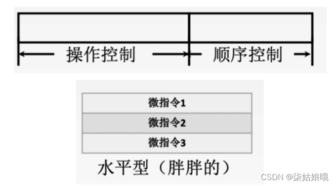
Vertical microinstructions
A micro instruction can only define one micro command , The specific function is specified by the micro operation code field
advantage : Microinstructions are short 、 Simple 、 Be regular , Easy to write microprograms ;
shortcoming : Microprogram length , Slow execution , Low work efficiency .

Mixed microinstruction
Add some less complex parallel operations on the basis of vertical type .
Microinstructions are shorter , Still easy to write ; Microprograms are not long , Faster execution .
Encoding mode of microinstruction
The encoding mode of microinstruction is also called the control mode of microinstruction , It refers to how to encode the control field of microinstruction , To form a control signal . The goal of coding is to ensure the speed , Try to shorten the microinstruction word length .
Direct code ( Direct control ) The way
In the operation control field of the microinstruction , Each bit represents a micro operation command
Someone is “1” Indicates that the control signal is valid
![[ Failed to transfer the external chain picture , The origin station may have anti-theft chain mechanism , It is suggested to save the pictures and upload them directly (img-ZHLLguX0-1657716190892)(C:\Users\DELL\AppData\Roaming\Typora\typora-user-images\image-20220712192048810.png)]](/img/36/8854b2e3c5710a9e2b8f97ced129b8.png)
advantage : Simple 、 intuitive , Fast execution , Good operation parallelism .
shortcoming : The microinstruction word length is too long ,n A micro command requires that the operation fields of the micro instruction have n position , Resulting in huge control and storage capacity .
Field direct encoding method
Divide the control fields of microinstructions into several “ paragraph ”, After each segment is decoded, a control signal is sent
The principle of micro command field segmentation :
① Mutually exclusive micro commands are divided into the same paragraph , Compatibility microcommands are divided into different segments .
② Each segment cannot contain too many bits of information , Otherwise, the complexity of decoding circuit and decoding time will be increased .
③ In general, each segment should have a status , Indicates that this field does not issue any micro commands . therefore , When the length of a field is 3 When a , At most, it can only mean 7 Two mutually exclusive micro commands , Usually use 000 It means no operation .
![[ Failed to transfer the external chain picture , The origin station may have anti-theft chain mechanism , It is suggested to save the pictures and upload them directly (img-NrSyMdaH-1657716190892)(C:\Users\DELL\AppData\Roaming\Typora\typora-user-images\image-20220712192536126.png)]](/img/0a/f27bb63061a34f5bb5ad1f819e8122.png)
advantage : It can shorten the word length of microinstructions . shortcoming : It is necessary to send micro commands after passing the decoding circuit , Therefore, it is slower than direct encoding .
Example
The controller of a computer is controlled by microprogram , The operation control field in microinstruction adopts field direct coding method , share 33 A micro command , constitute 5 Mutex classes , Each contains 7、3、12、5 and 6 A micro command , Then how many bits does the operation control field have at least ?
The first 1 Mutually exclusive classes are 7 A micro command , To set aside 1 States indicate no operation , So we need to express 8 Different states , So we need 3 Binary bits .
And so on , Back 4 Mutually exclusive classes need to be taught 4、13、6、7 Different states , They correspond to each other 2、4、3、3 Binary bits .
Therefore, the total number of digits of the operation control field is 3+2+4+3+3 = 15 position
Tips: If direct coding method is adopted , Then the control field needs 33 position
Field indirect encoding method
Some micro commands in one field need to be interpreted by some micro commands in another field , Because it is not directly decoded by the field , So it is called field indirect coding , Also known as implicit coding .
advantage : The microinstruction word length can be further shortened . shortcoming : It weakens the parallel control ability of microinstructions , Therefore, it is usually used as an auxiliary means of field direct coding .
![[ Failed to transfer the external chain picture , The origin station may have anti-theft chain mechanism , It is suggested to save the pictures and upload them directly (img-SzRLKb9G-1657716190893)(C:\Users\DELL\AppData\Roaming\Typora\typora-user-images\image-20220712192814117.png)]](/img/05/a29e1bcddb662d56a6645982a11059.png)
The address formation method of microinstruction
1. The lower address field of the microinstruction indicates
Set a lower address field in the microinstruction format , The address of the subsequent microinstruction is directly indicated by the lower address field of the microinstruction , This way is also known as the way of judgment .
2. Form according to the opcode of the machine instruction
When the machine instruction is fetched to the instruction register , The address of the micro instruction is formed by the operation code through the micro address forming part .
3. Incremental counter method (CMAR )+1→CMAR
4. Branch transfer
Transfer mode : Specify the criteria ; Transfer address : Indicate the destination after successful transfer .
![[ Failed to transfer the external chain picture , The origin station may have anti-theft chain mechanism , It is suggested to save the pictures and upload them directly (img-FSkEMcW1-1657716190893)(C:\Users\DELL\AppData\Roaming\Typora\typora-user-images\image-20220712193233702.png)]](/img/28/e5540cd3cfe4ec4a3671aad959009d.png)
5. Test network
![[ Failed to transfer the external chain picture , The origin station may have anti-theft chain mechanism , It is suggested to save the pictures and upload them directly (img-vjXD5ZiY-1657716190893)(C:\Users\DELL\AppData\Roaming\Typora\typora-user-images\image-20220712193311983.png)]](/img/a4/28af3a0eaeea7ea8f9d33180cffc31.png)
6. Microprogram entry address generated by hardware
First microinstruction address ― Produced by specialized hardware ( Use special hardware records to get the first address of the periodic microprogram ) Interrupt cycle ― Interrupt cycle microprogram first address generated by hardware ( Record with special hardware )
Example – The way of judging
![[ Failed to transfer the external chain picture , The origin station may have anti-theft chain mechanism , It is suggested to save the pictures and upload them directly (img-TDBFOkp8-1657716190894)(C:\Users\DELL\AppData\Roaming\Typora\typora-user-images\image-20220712193512988.png)]](/img/59/4e4bd55531afbba536115a94fa9b45.png)
Design of microprogram control unit
Design of microprogram control unit
![[ Failed to transfer the external chain picture , The origin station may have anti-theft chain mechanism , It is suggested to save the pictures and upload them directly (img-mcfH00Sl-1657716190894)(C:\Users\DELL\AppData\Roaming\Typora\typora-user-images\image-20220712200046271.png)]](/img/e6/ba1680109b5a86677f73c8f7bc7e6c.png)
![[ Failed to transfer the external chain picture , The origin station may have anti-theft chain mechanism , It is suggested to save the pictures and upload them directly (img-1K45yjq1-1657716190894)(C:\Users\DELL\AppData\Roaming\Typora\typora-user-images\image-20220712194418698.png)]](/img/10/d3fc65fe5bd8a67cfee622e84b6a56.png)
![[ Failed to transfer the external chain picture , The origin station may have anti-theft chain mechanism , It is suggested to save the pictures and upload them directly (img-i6WDQurS-1657716190895)(C:\Users\DELL\AppData\Roaming\Typora\typora-user-images\image-20220712195120469.png)]](/img/f4/35e5d99028ed6374204da6da1be0b1.png)
obviously , Microprogrammed controllers are slower than hardwired controllers
Microprogramming classification
1. Static microprogramming and dynamic microprogramming
Static microprograms do not need to be changed , use ROM
Changing machine instructions dynamically by changing microinstructions and microprograms is conducive to simulation , use EPROM
2. Nanoprogramming
Basic concepts of nanoprogramming
Microprogramming uses microprograms to interpret machine instructions
Nanoprogramming uses nanoprograms to interpret microprograms
Comparison between hard wiring and microprograms
![[ Failed to transfer the external chain picture , The origin station may have anti-theft chain mechanism , It is suggested to save the pictures and upload them directly (img-JpqsZVu4-1657716190895)(C:\Users\DELL\AppData\Roaming\Typora\typora-user-images\image-20220712200450552.png)]](/img/6d/3e696e5abd002a8ad617418c087d76.png)
The basic concept of instruction pipeline
![[ Failed to transfer the external chain picture , The origin station may have anti-theft chain mechanism , It is suggested to save the pictures and upload them directly (img-EqD4p1sY-1657716190895)(C:\Users\DELL\AppData\Roaming\Typora\typora-user-images\image-20220713180753842.png)]](/img/37/f44ed9229b968425883c752364e30b.png)
Ideal situation : Each stage takes the same time ; At the end of each stage, you can immediately enter the next stage .
Definition of instruction pipeline
The execution of an instruction can be divided into multiple stages ( Or process ). Depending on the computer , The specific classification is also different .
![[ Failed to transfer the external chain picture , The origin station may have anti-theft chain mechanism , It is suggested to save the pictures and upload them directly (img-oj2sH8KX-1657716190896)(C:\Users\DELL\AppData\Roaming\Typora\typora-user-images\image-20220713175024263.png)]](/img/23/3bac9963e0b2518002c439c7fc5c07.png)
Fingering : according to PC Content access main storage , Take out an instruction and send it to IR in .
analysis : Decode the instruction opcode , Form the effective address of the operand according to the given addressing method and the content in the address field EA, And from the valid address EA Fetch operand from .
perform : According to the opcode field , Complete the functions specified in the instruction , That is, write the operation result to the general register or main memory .
characteristic : The hardware used in each stage is different .
Set index 、 analysis 、 perform 3 The time of each stage is equal , use t Express , Analyze according to the following execution methods n Execution time of instructions :
![[ Failed to transfer the external chain picture , The origin station may have anti-theft chain mechanism , It is suggested to save the pictures and upload them directly (img-Bxqt7Oed-1657716190897)(C:\Users\DELL\AppData\Roaming\Typora\typora-user-images\image-20220713175305935.png)]](/img/73/63bf443fd078ff893528025f10a878.png)
Traditional Feng · Neumann machine adopts sequential execution , Also known as serial execution .
advantage : Simple control , The cost of hardware is small .
shortcoming : The speed of executing instructions is slow , At any moment , There is only one instruction executing in the processor , The utilization rate of each functional component is very low .
![[ Failed to transfer the external chain picture , The origin station may have anti-theft chain mechanism , It is suggested to save the pictures and upload them directly (img-x4lGSirp-1657716190897)(C:\Users\DELL\AppData\Roaming\Typora\typora-user-images\image-20220713175348241.png)]](/img/54/b16468a3734e4c5e409b493d5a473c.png)
advantage : The execution time of the program is shortened 1/3, The utilization rate of each functional component is significantly improved .
shortcoming : It needs to pay a high cost of hardware , The control process is also more complex than sequential execution .
![[ Failed to transfer the external chain picture , The origin station may have anti-theft chain mechanism , It is suggested to save the pictures and upload them directly (img-mZPXAI57-1657716190897)(C:\Users\DELL\AppData\Roaming\Typora\typora-user-images\image-20220713175448893.png)]](/img/2b/9d4afc0cfaa443d64ad1f0911f1451.png)
Compared with sequential execution , The execution time of instructions is shortened by nearly 2/3. This is an ideal way to execute instructions , Under normal circumstances , There are 3 Instructions are executing .
notes : The execution process of each instruction can also be divided into 4 Or 5 Stages , Divide into 5 The second stage is a common practice .
Pipeline representation
[ Failed to transfer the external chain picture , The origin station may have anti-theft chain mechanism , It is suggested to save the pictures and upload them directly (img-VkNlUwgC-1657716190898)(C:\Users\DELL\AppData\Roaming\Typora\typora-user-images\image-20220713175752033.png)]
It is mainly used to analyze the instruction execution process and the factors affecting the pipeline

It is mainly used to analyze the performance of pipeline 
Pipeline performance index
Throughput rate
![[ Failed to transfer the external chain picture , The origin station may have anti-theft chain mechanism , It is suggested to save the pictures and upload them directly (img-pFXQXITs-1657716190898)(C:\Users\DELL\AppData\Roaming\Typora\typora-user-images\image-20220713180247964.png)]](/img/30/501bdaabf3f425602fd6238eb5e312.png)
Speedup ratio
![[ Failed to transfer the external chain picture , The origin station may have anti-theft chain mechanism , It is suggested to save the pictures and upload them directly (img-oqixs2ri-1657716190899)(C:\Users\DELL\AppData\Roaming\Typora\typora-user-images\image-20220713180414851.png)]](/img/c4/ff93c36ee1521ea938290c5a037814.png)
efficiency
![[ Failed to transfer the external chain picture , The origin station may have anti-theft chain mechanism , It is suggested to save the pictures and upload them directly (img-YMPBbFOH-1657716190899)(C:\Users\DELL\AppData\Roaming\Typora\typora-user-images\image-20220713180653432.png)]](/img/38/702726e013b1c1cb7a428f3ac19a8b.png)
Five segment instruction pipeline
Machine cycle setting
There must be a buffer register behind each function segment of the pipeline , Or latch , Its function is to save the execution result of this flow segment , For the next flow section .
![[ Failed to transfer the external chain picture , The origin station may have anti-theft chain mechanism , It is suggested to save the pictures and upload them directly (img-VleYX921-1657716190899)(C:\Users\DELL\AppData\Roaming\Typora\typora-user-images\image-20220713181103834.png)]](/img/a5/3cd1d8c6adf4e0dc60914fffe9d940.png)
To facilitate the design of the assembly line , Take the time of each phase as the same , Take the longest time . That is, the machine cycle should be set to 100ns.
Ideally , Every machine cycle ( Function segment ) It only takes one clock cycle .
Five common types of instructions in exams :· Operation instruction 、LOAD Instructions 、STORE Instructions 、 Conditional transfer instructions 、 Unconditional transfer instructions
Only the last command enters ID After paragraph , The next command will start IF paragraph , Otherwise it will cover lF The contents of the segment latch
Operation class instruction execution process
![[ Failed to transfer the external chain picture , The origin station may have anti-theft chain mechanism , It is suggested to save the pictures and upload them directly (img-ghm2zEub-1657716190900)(C:\Users\DELL\AppData\Roaming\Typora\typora-user-images\image-20220713181155561.png)]](/img/40/48afc42165f4198fd54ddd01d26532.png)
![[ Failed to transfer the external chain picture , The origin station may have anti-theft chain mechanism , It is suggested to save the pictures and upload them directly (img-yeTIfI2M-1657716190900)(C:\Users\DELL\AppData\Roaming\Typora\typora-user-images\image-20220713181252733.png)]](/img/87/948c509e007e39ad0fe00a5b9c3c54.png)
Operation instruction
IF: according to PC From instructions Cache Take the command to lF Segment latch
ID: Take the operands to ID Segment latch
EX: operation , Store the results in EX Segment latch
M: Empty section
WB: Write the result back to the specified register
![[ Failed to transfer the external chain picture , The origin station may have anti-theft chain mechanism , It is suggested to save the pictures and upload them directly (img-PuQDIA4a-1657716190901)(C:\Users\DELL\AppData\Roaming\Typora\typora-user-images\image-20220713181408050.png)]](/img/4f/0cba94f1af8d50bb5666da50412ea6.png)
LOAD The execution of instructions
![[ Failed to transfer the external chain picture , The origin station may have anti-theft chain mechanism , It is suggested to save the pictures and upload them directly (img-iELGmo71-1657716190901)(C:\Users\DELL\AppData\Roaming\Typora\typora-user-images\image-20220713181830728.png)]](/img/f7/d063eedbe0cd11e0e1aee08dcfcdb3.png)
![[ Failed to transfer the external chain picture , The origin station may have anti-theft chain mechanism , It is suggested to save the pictures and upload them directly (img-8IHjZ0K8-1657716190901)(C:\Users\DELL\AppData\Roaming\Typora\typora-user-images\image-20220713182153117.png)]](/img/e3/d181eb33647218041727235285bf78.png)
LOAD Instructions
IF: according to PC From instructions Cache Take the command to IF Segment latch
ID: Put the value of the base register in the latch A, Put the value of the offset in Imm
EX: operation , Get a valid address
M: From data cache And put it into the latch
WB: Write the fetched number back to the register
Usually ,RISC The processor only has “ Count LOAD” and “ Inventory STORE” Instructions to access main memory
STORE The execution of instructions
![[ Failed to transfer the external chain picture , The origin station may have anti-theft chain mechanism , It is suggested to save the pictures and upload them directly (img-nUrxzY4T-1657716190902)(C:\Users\DELL\AppData\Roaming\Typora\typora-user-images\image-20220713182405977.png)]](/img/b2/294a07ca327b1acb1458a3dd977794.png)
![[ Failed to transfer the external chain picture , The origin station may have anti-theft chain mechanism , It is suggested to save the pictures and upload them directly (img-RxaIJeRL-1657716190903)(C:\Users\DELL\AppData\Roaming\Typora\typora-user-images\image-20220713182438792.png)]](/img/a9/a5a126667957142f68fc9f19a55110.png)
STORE Instructions
lF: according to PC From instructions Cache Take the command to IF Segment latch
ID: Put the value of the base register in the latch A, Put the value of the offset in Imm. Place the number to be saved in the B
EX: operation , Get a valid address . And put the latch B Put the contents of into the latch Store.
M: Write data Cache
WB: Empty section
The execution of conditional transfer instructions
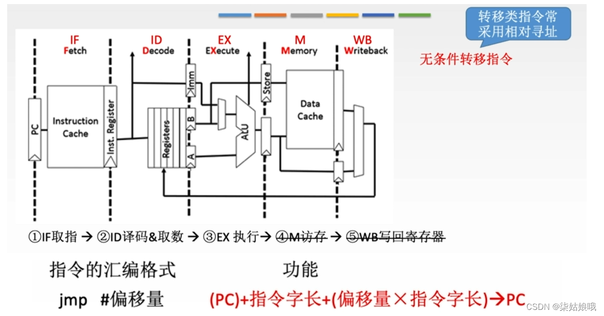
Transfer class instructions often use relative addressing
![[ Failed to transfer the external chain picture , The origin station may have anti-theft chain mechanism , It is suggested to save the pictures and upload them directly (img-0xPfZNkH-1657716190904)(file://C:\Users\DELL\AppData\Roaming\Typora\typora-user-images\image-20220713182405977.png?lastModify=1657708095)]](/img/54/687bac7bbbc3e0fde58f35aec48dec.png)
![[ Failed to transfer the external chain picture , The origin station may have anti-theft chain mechanism , It is suggested to save the pictures and upload them directly (img-BblshY04-1657716190904)(C:\Users\DELL\AppData\Roaming\Typora\typora-user-images\image-20220713183213721.png)]](/img/92/d88000bf5c017f6a8ee1c46b9edc86.png)
Conditional transfer instructions
IF: according to PC From instructions cache Take the command to IF Segment latch
ID: The two numbers that are compared are put into the latch A、B; The offset is placed in Imm
EX: operation , Compare two numbers
M: The target PC Write the value back to PC
WB: Empty section
Many textbooks write back PC The functional segment of is called “WrPC paragraph ”, Its time-consuming ratio M The paragraph is shorter , Can be arranged in M Complete in a period of time
The execution of an unconditional transfer instruction
Unconditional transfer instructions
lF: according to PC From instructions Cache Take the command to IF Segment latch
ID: The offset is placed in Imm
EX: The target Pc Write the value back to PC( The picture on the left is not complete )
M: Empty section
WB: Empty section
“WrPC paragraph ” Time ratio EX The paragraph is shorter , Can be arranged in EX Complete in a period of time .WrPC The sooner the section is completed , The more control conflicts can be avoided . Of course , There are also places where WB It took some time to modify PC Value
Example
![[ Failed to transfer the external chain picture , The origin station may have anti-theft chain mechanism , It is suggested to save the pictures and upload them directly (img-eq7CJvTW-1657716190906)(C:\Users\DELL\AppData\Roaming\Typora\typora-user-images\image-20220713184127514.png)]](/img/c0/f17091e37b618755a4fb5080017686.png)
Influencing factors and classification of instruction pipeline
![[ Failed to transfer the external chain picture , The origin station may have anti-theft chain mechanism , It is suggested to save the pictures and upload them directly (img-xBtZORlJ-1657716190906)(C:\Users\DELL\AppData\Roaming\Typora\typora-user-images\image-20220713202623848.png)]](/img/3e/503dba7d35e1dc099454e4f7626f3f.png)
![[ Failed to transfer the external chain picture , The origin station may have anti-theft chain mechanism , It is suggested to save the pictures and upload them directly (img-w5eA940K-1657716190906)(C:\Users\DELL\AppData\Roaming\Typora\typora-user-images\image-20220713204115687.png)]](/img/47/b61ae3733caf4307fed252c35ef8c2.png)
There must be a buffer register behind each function segment of the pipeline , Or latch , Its function is to save the execution result of this flow segment , For the next flow section .
![[ Failed to transfer the external chain picture , The origin station may have anti-theft chain mechanism , It is suggested to save the pictures and upload them directly (img-OUHBrfHM-1657716190907)(C:\Users\DELL\AppData\Roaming\Typora\typora-user-images\image-20220713185629555.png)]](/img/8f/f3e75b05e7eab2cd25e867624ceabb.png)
Factors affecting the assembly line
Structure related ( Resource conflict )
The conflict caused by multiple instructions competing for the same resource at the same time is called structure dependent .
![[ Failed to transfer the external chain picture , The origin station may have anti-theft chain mechanism , It is suggested to save the pictures and upload them directly (img-bC24UE9G-1657716190907)(C:\Users\DELL\AppData\Roaming\Typora\typora-user-images\image-20220713200629944.png)]](/img/86/003e78190ad45bbb2e06374c31ddfb.png)
terms of settlement :
1. The latter related instruction pauses for one cycle
2. Duplicate resource configuration : Data storage + Instruction memory
Data related ( Data conflict )
Data correlation refers to... In a program , There is a situation that the next instruction cannot be executed until the previous instruction is executed , Then these two instructions are data related .
![[ Failed to transfer the external chain picture , The origin station may have anti-theft chain mechanism , It is suggested to save the pictures and upload them directly (img-nolQnha2-1657716190907)(C:\Users\DELL\AppData\Roaming\Typora\typora-user-images\image-20220713201335048.png)]](/img/77/e5a5ad944513d87c0e421ca9cecad8.png)
terms of settlement :
1. Pause the instructions related to the encountered data and their subsequent instructions for one to several clock cycles , Continue until the data related problems disappear . It can be divided into hardware blocking (stall) And software insertion “NOP” The two methods .
2. Data bypass technology : Forwarding mechanism
![[ Failed to transfer the external chain picture , The origin station may have anti-theft chain mechanism , It is suggested to save the pictures and upload them directly (img-uV3XWq9N-1657716190907)(C:\Users\DELL\AppData\Roaming\Typora\typora-user-images\image-20220713201856747.png)]](/img/f5/a368b9dcde9d99417ff9a7bc084e37.png)
3. Compile optimization : Through the compiler to adjust the order of instructions to solve the data correlation .
![[ Failed to transfer the external chain picture , The origin station may have anti-theft chain mechanism , It is suggested to save the pictures and upload them directly (img-rokCIGs9-1657716190908)(C:\Users\DELL\AppData\Roaming\Typora\typora-user-images\image-20220713202021255.png)]](/img/b0/6690b5d2b8c9505ad6b6d02e7f39a9.png)
Control related ( Control conflict )
When the pipeline encounters transfer instructions and other changes PC When the current is cut off due to the instruction of value , Will cause control related .
terms of settlement :
1. Branch prediction of branch instruction . Simple prediction ( Always guess ture or false) 、 Dynamic prediction ( Dynamically adjust according to historical conditions )
![[ Failed to transfer the external chain picture , The origin station may have anti-theft chain mechanism , It is suggested to save the pictures and upload them directly (img-EOGJov4V-1657716190908)(C:\Users\DELL\AppData\Roaming\Typora\typora-user-images\image-20220713202329576.png)]](/img/03/c75e8d56b4191c63791bdbb997fff5.png)
2. Prefetch the target instruction in the direction of successful and unsuccessful control flow
3. Accelerate and advance the formation of condition codes
4. Improve the accuracy of the transfer direction
Pipeline classification
1. Component functional level 、 Processor level and inter processor level pipeline
According to the level of pipeline , Pipeline can be divided into component function level pipeline 、 Processor level pipeline and inter processor pipeline .
Component function level pipelining is a pipelining method that combines complex arithmetic and logic operations . for example , Floating point addition operations can be divided into order differences 、 Antithetic order 、 Mantissa addition and result normalization 4 Sub process .
Processor level pipelining is to divide an instruction interpretation process into several sub processes , As mentioned above, take the finger 、 decoding 、 perform 、 Deposit and write back 5 Sub process .
Inter processor pipelining is a kind of macro pipelining , Each processor performs a specific task , The results obtained by each processor should be stored in the memory shared with the next processor .
2. Single function pipeline and multi-function pipeline
Functions that can be completed according to the assembly line , Assembly line can be divided into single function assembly line and multi-function assembly line .
Single function pipeline refers to a pipeline that can only realize one fixed special function ;
Multi function pipeline refers to a pipeline that can realize multiple functions at the same time or at different times through different connection methods between segments .
3. Dynamic pipeline and static pipeline
According to the connection mode between segments at the same time , Pipeline can be divided into static pipeline and dynamic pipeline .
Static pipeline means that at the same time , Each section of the pipeline can only work according to the connection mode of the same function .
Dynamic pipeline means that at the same time , When some segments are performing some operation , Other segments are performing another operation . This is good for improving the efficiency of the pipeline , But it will make the pipeline control very complicated .
4. Linear pipeline and nonlinear pipeline
Whether there is feedback signal between each functional section of the pipeline , Pipeline can be divided into linear pipeline and nonlinear pipeline .
In linear pipeline , From input to output , Each functional segment is allowed to pass only once , There is no feedback loop .
Nonlinear pipeline with feedback loop , From input to output , Some functional segments will pass through the pipeline several times , This pipeline is suitable for linear recursive operation .
Multi engine technology of pipeline
Superscalar Technology
![[ Failed to transfer the external chain picture , The origin station may have anti-theft chain mechanism , It is suggested to save the pictures and upload them directly (img-NmrT2nhs-1657716190909)(C:\Users\DELL\AppData\Roaming\Typora\typora-user-images\image-20220713203507896.png)]](/img/fb/aa1ba48d6a973b4ce702bc18201db0.png)
Multiple independent instructions can be concurrent in each clock cycle
To configure multiple features
The execution order of instructions cannot be adjusted
By compiling optimization technology , Match instructions that can be executed in parallel
Superfluid technology
![[ Failed to transfer the external chain picture , The origin station may have anti-theft chain mechanism , It is suggested to save the pictures and upload them directly (img-0lgjUJOL-1657716190909)(C:\Users\DELL\AppData\Roaming\Typora\typora-user-images\image-20220713203820833.png)]](/img/31/ed7cea583f8abd177f64b7d0a23481.png)
In another cycle (3 paragraph )
A function unit is used multiple times in a clock cycle ( 3 Time )
The execution order of instructions cannot be adjusted
Solve optimization problems by compiling programs
Very long instruction words
![[ Failed to transfer the external chain picture , The origin station may have anti-theft chain mechanism , It is suggested to save the pictures and upload them directly (img-xOjJL88w-1657716190909)(C:\Users\DELL\AppData\Roaming\Typora\typora-user-images\image-20220713203856141.png)]](/img/33/c07b554c07c42fd308ae39779c25bc.png)
The compiler digs out the potential parallelism between instructions , Combine multiple instructions that can operate in parallel into one
Extra long instruction word with multiple opcode fields ( Up to hundreds )
Multiple processing units are used
decoding 、 perform 、 Deposit and write back 5 Sub process .
Inter processor pipelining is a kind of macro pipelining , Each processor performs a specific task , The results obtained by each processor should be stored in the memory shared with the next processor .
2. Single function pipeline and multi-function pipeline
Functions that can be completed according to the assembly line , Assembly line can be divided into single function assembly line and multi-function assembly line .
Single function pipeline refers to a pipeline that can only realize one fixed special function ;
Multi function pipeline refers to a pipeline that can realize multiple functions at the same time or at different times through different connection methods between segments .
3. Dynamic pipeline and static pipeline
According to the connection mode between segments at the same time , Pipeline can be divided into static pipeline and dynamic pipeline .
Static pipeline means that at the same time , Each section of the pipeline can only work according to the connection mode of the same function .
Dynamic pipeline means that at the same time , When some segments are performing some operation , Other segments are performing another operation . This is good for improving the efficiency of the pipeline , But it will make the pipeline control very complicated .
4. Linear pipeline and nonlinear pipeline
Whether there is feedback signal between each functional section of the pipeline , Pipeline can be divided into linear pipeline and nonlinear pipeline .
In linear pipeline , From input to output , Each functional segment is allowed to pass only once , There is no feedback loop .
Nonlinear pipeline with feedback loop , From input to output , Some functional segments will pass through the pipeline several times , This pipeline is suitable for linear recursive operation .
Multi engine technology of pipeline
Superscalar Technology
[ Outside the chain picture transfer in …(img-NmrT2nhs-1657716190909)]
Multiple independent instructions can be concurrent in each clock cycle
To configure multiple features
The execution order of instructions cannot be adjusted
By compiling optimization technology , Match instructions that can be executed in parallel
Superfluid technology
[ Outside the chain picture transfer in …(img-0lgjUJOL-1657716190909)]
In another cycle (3 paragraph )
A function unit is used multiple times in a clock cycle ( 3 Time )
The execution order of instructions cannot be adjusted
Solve optimization problems by compiling programs
Very long instruction words
[ Outside the chain picture transfer in …(img-xOjJL88w-1657716190909)]
The compiler digs out the potential parallelism between instructions , Combine multiple instructions that can operate in parallel into one
Extra long instruction word with multiple opcode fields ( Up to hundreds )
Multiple processing units are used
边栏推荐
- 审视自己投资的路
- 5. Is the asynctool framework flawed?
- 【NoSQL】NoSQL之redis配置与优化(简单操作)
- What happens when you get stuck compiling and installing MySQL database in Linux system?
- GraphQL初识
- Systick timer basic learning and hand tearing code
- 【单片机仿真】(一)Proteus8.9 安装教程
- [MCU simulation] (XXI) dB (define byte) - define byte
- DDD 超越 MVC了吗
- RESNET learning notes
猜你喜欢

【单片机仿真】(二十)ORG — 设置起始地址

无法访问此网站无法找到DNS地址DNS_PROBE_STARTED怎么办?

Advanced usage of the responsibility chain pattern

JDBC连接Mysql数据库

一个优酷VIP会员帐号可以几个人用的设备同时登录如何共享多人使用优酷会员账号?

2002 - Can‘t connect to server on ‘127.0.0.1‘ (36)

HCIA_ Nat experiment

DHCP principle and configuration

Code demonstration of fcos face detection model in openvino

Pytorch best practices and code templates
随机推荐
PyTorch最佳实践和代码模板
DHCP principle and configuration
深入理解机器学习——类别不平衡学习(Imbalanced Learning):样本采样技术-[人工采样技术之ADASYN采样法]
【单片机仿真】(六)寻址方式 — 变址寻址与相对寻址
while 循环
无线用的鉴权代码
SysTick定时器的基础学习以及手撕代码
多锻炼身体有好处
D. Permutation Restoration(贪心/双指针/set)
BiSeNetV2-面部分割
yolov6 学习初篇
Systick timer basic learning and hand tearing code
[MCU simulation] (XVI) control transfer instructions - unconditional transfer instructions, conditional transfer instructions
10. System safety and Application
[PHP] tp6 multi table connection query
Oracle gets the last and first data (gets the first and last data by time)
First blog ----- self introduction
Understand JVM garbage collection in one article
4年开发二面美团最终败给:volatile关键字作用和原理这道面试题
ncnn DataReader&Extractor&blob