当前位置:网站首页>Simulation of overvoltage protection (OVP) circuit based on PMOS
Simulation of overvoltage protection (OVP) circuit based on PMOS
2022-07-19 13:32:00 【Embedded maker workshop】
The circuit comes from sun, a male teacher of Engineering ,B Station video link : Click the jump
The use of protues It is verified by simulation , The following figure shows the circuit model

1. Normal voltage input 5V

Circuit input 5V when , The circuit is normally connected , The input voltage is equal to the output voltage . At this time, the input voltage is less than the regulated value of the regulator , The zener diode does not work in the stabilized voltage state .PNP Transistor's BE The pressure difference between is 0, Do not meet the conduction voltage , So at this time, the triode is off , therefore PMOS Of G Polar quilt R3 Pull down resistor pull down , At the moment PMOS Conduction , because Vgs<Vgs(th). What needs to be noted here is , During normal operation Vgs It should be equal to the input voltage , So for PMOS The type selection of the needs to pay attention to its parameters Vgs(th), Ensure complete conduction during normal operation .
2. Input overvoltage 12V
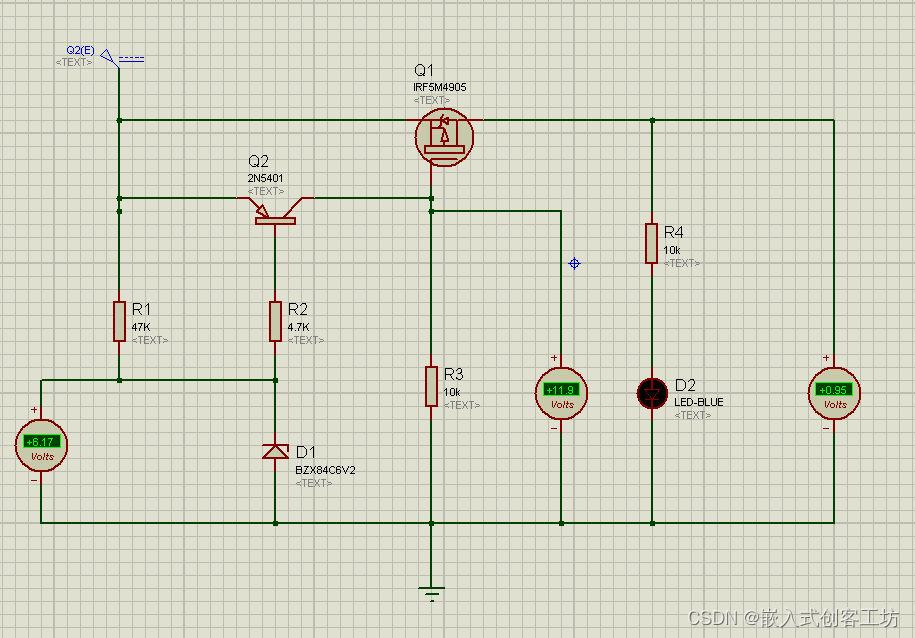
Circuit input 12V when , The circuit is cut off .( I don't know why there is still 0.95V Output , Is there a problem with the simulation software ?) At this time, the zener diode is normally stabilized , Triode voltage Veb= Input -- Voltage stabilizing value . as long as Vbe Greater than the on voltage , The triode will turn on , Input 12V when ,Veb=12--6.2=5.8V, The display meets the conduction conditions , Therefore, when the triode is turned on, the resistance R3 Act as a pull-up resistor , take PMOS Pull up to the input voltage , Lead to Vgs=0,PMOS No conduction , Realize circuit disconnection .
Overall analysis of the circuit , In fact, the voltage value of overvoltage shutdown is related to the voltage stabilizing value of Zener diode , Its overvoltage shutdown value = Voltage stabilizing value + Triode on voltage . The conduction voltage of triode is basically 0.6 To 0.7V, So for the design of overvoltage protection circuit , It mainly changes the voltage stabilizing value of the voltage stabilizing tube to realize . about R1、R2 Also pay attention to the value of , When the regulator tube stabilizes the pressure , That is, when the circuit is over-voltage , The current through the zener diode should be guaranteed >1mA, Because the current cannot be too small when the voltage regulator is normally stabilized .
The picture below is BZX84C Pressure stabilizing curve of series stabilizer , When the current is small, it shows the trend of linear voltage stabilization .

边栏推荐
- 565. Array nesting
- Onvif protocol related: 2.1.3 get the stream address in none mode
- Responsive Zhimeng template logistics and freight service website
- ArrayList underlying analysis
- 大家好,问一下数据库没开始binlog如何实时同步么,有没有好的方案
- OpenSSL操作
- Method of converting video format to ffmpeg and exporting GIF dynamic graph
- Computer dial-up Internet access
- Unveiling secrets of matrixcube 101 - functions and architecture of matrixcube
- Code after annotation of hands-on deep learning (Second Edition) [continuous update]
猜你喜欢

Onvif protocol related: 2.1.2 get screenshot URL in none mode

Panasonic A6 servo driver external absolute value grating ruler full closed loop parameter setting
How to upgrade Flink job gracefully?
 [email protected] (FE) composite nan"/>
Metal organic framework material / polymer composite zif-8/p (TDA co HDA) | zinc oxide [email protected] (FE) composite nan

El table column drag and drop (no need to introduce other plug-ins)

codeforce:A. Doremy‘s IQ【反向贪心】

LeetCode 0117. 填充每个节点的下一个右侧节点指针 II

XML modeling (easy to learn)

Interviewer: is it acceptable to transfer to go?

565. Array nesting
随机推荐
LeetCode 0117. Populate the next right node pointer II of each node
Li Kou 70 - climbing stairs - Dynamic Planning
onvif协议相关:3.1.4 Digest方式获取流地址
AcWing 257. Explanation of prisoner detention (bipartite picture)
模板虚拟机环境准备
Principle of voice communication network
Unveiling secrets of matrixcube 101 - functions and architecture of matrixcube
Force buckle 64 minimum path sum -- Introduction to dynamic programming
El table column drag and drop (no need to introduce other plug-ins)
STL string输出与修改
语音通信网络的原理
torch. utils. data. Dataloader description
Transphorm的表面贴装封装产品系列增加行业标准TO-263 (D2PAK)封装产品,扩大SuperGaN平台的优势
大家好,问一下数据库没开始binlog如何实时同步么,有没有好的方案
ssh无密钥登录
【考研词汇训练营】Day 6 —— eventually,state,create,productivity,stimulate
Onvif protocol related: 3.1.3 get screenshot URL in digest mode
使用case语句时会产生锁存器的情况
STL string查找子串
【码蹄集新手村 600 题】输出时的左对齐,右对齐